Ultimate Guide to Tramming a Milling Machine Head
Tramming is an important procedure for manual milling machines, to ensure the tool is vertical to the work table by changing the mill head utilizing measurement tools. How to tram a mill head? Here you can take a look at the devices, approaches, procedures, and also actions for tramming a milling machine head.
Table of Contents
What is Tramming?
The cable car is the squareness of the mill head to the table, and also tramming is the process of making even the head of the milling device to the table or readjusting the mill head to be square. Tramming a milling machine head can make sure the cutting tool is perpendicular to the table surface area in both X and Y directions, make certain the machine-made surface areas are mutually perpendicular as well as stay clear of forming saw tooth patterns externally of CNC milled parts. The best goal is to device the milling components appropriately. Check the tram of a mill head frequently, particularly when the device includes a swivel head for cutting at angles.
The Tools of CNC Tramming
- Dial Indicator is the tool used in tramming a milling machine head, connected to the chuck, as well as utilized to identify the alignment of the mill head and the worktable.
- Mill Wrench, which made use of to loosen the quill as well as tighten up for modification of the various bolts on the mill head.
- Sign holder.
- Parallels.

All kinds Methods of Tramming a Milling Machine Head
Different approaches adopt different tools and also concepts, but all show if the mill head needs to be readjusted through the readings or various other external sensations.
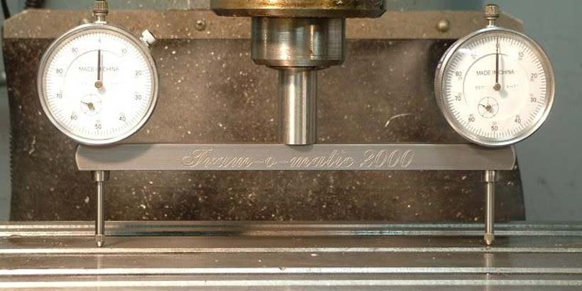
- Tramming a mill head with pin squares is fast and accurate. Adjust as well as zero both indicators prior to starting. Put the spindle square in the collet chuck and also lower the quill until 2 indicators touch the table, inspect whether the analyses on 2 indicators coincide, otherwise, adjust the head direction, then turn the pin 90 levels as well as check the other axis.
- Examining the mill’s tram with a Dial test sign (DTI) is very usual, attach it to the spindle of the milling machine and inspect the tram through the analyses of the indication on 2 points of the X-axis which on two factors of the Y-axis coincide. If the readings are various, adjust the mill head till they come to be the same.
- Put a machinist square or cylinder square (a lot more specific) on the mill table as well as reduced your device’s quill, position the vertical side of the square against the quill. Inspect whether the surface area of the quill is entirely touching the square, otherwise, adjust the milling machine head. Check both the X and Y-axis. This method is quick and also straightforward.
Process and Steps of Tramming a Milling Machine Head
Tramming for the Y-axis
- Loosen the four clamping bolts on the front of the mill to enable the head to relocate.
- Transform the adjusting bolt on the top of the mill.
- Change the mill head to the no on the protractor by turning the bolt.
- Attach the dial indicator to the chuck, and lower the chuck up until the sign touches the table surface.
- Readjust the table elevation till the indicator preload at 0.005″ to 0.010″.
- Setting the indicator at the best side of the worktable.
- No dial indicator.
- Revolve the chuck so make the indicator at the left side of the table.
- Identify where the head requires to be moved according to the analysis: favorable reading suggests the head requires to be rotated in clockwise, negative analysis, relocates counter-clockwise.
- Readjust the mill head to make the reading difference between front and also rear disappears than 0.002″.
- Re-tighten the clamping bolts, while maintaining the mill head is fixed.
Tramming for the X-axis
- Loosen the 6 securing bolts on two sides of the mill making use of the mill wrench.
- Tighten up the loosened-up screws by hand plus a quarter turn with the wrench.
- The adjustment bolts are made use of to move the mill head up and down around the X-axis.
- Usage 2 protractors to indicate basic alignment. The bigger one on the mill head ought to line up with the zero pens on the rounded protractor on the mill body.
- Place the dial indicator to the back of the mill table and action on the immaculate surface of the table: preload at 0.005″ to 0.010″ and also zero the dial indicator.
- Ensure the spindle is neutral, revolve it to make the dial indicator on the front of the table, maintain the components affixed.
- Figure out the direction the mill head to go according to dial turning: dial moves in clockwise needs mill head will certainly need to be adjusted up, while a counter-clockwise analysis requires descending adjustment.
- Readjust the mill head to ensure that 1/2 the distinction between the back and also front measurements.
- Zero the dial indication once more in the same placement as before.
- Remain to readjust the mill head till the difference of the analyses is not more than 0.002 inches.
- Tighten up the screws evenly, avoid the mill head from relocating.