Guide to CNC Machine Design
CNC machined parts usually begin with designs or illustrations that can be created by the CAD software program and saved as a DXF file, which is converted to G-code (CNC programming language), running and also managing the machines and also cutters. Here we bring a CNC machining design guide with steps, methods, pointers, tips, and restrictions.
What Does CNC Mean in Machining?
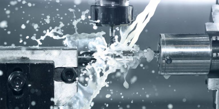
CNC is the acronym of Computer Numerical Control, the electronic automatic machinery can be utilized to eliminate the product from a blank according to a certain design or do specific machining operations according to the programming, the computer will certainly convert the CAD design into numbers (visuals collaborates) to manage the activity of the cutting device of the CNC machine (mill, turret, router, etc.).
The process of CNC machining:
- Design a drawing of the CNC component.
- Convert the layout to programs language.
- Run-on the CNC machine.
How to Make CNC Layout
- Search, collect and categorize the illustrations, images, photos, ideas or any kind of valuable resources for reference when producing a suitable CAD model.
- Determine the position for locating part zero, as well as placed the part in the CAD design, make the 0, 0, 0 beginning goes to part zero.
- Create a preliminary version of the CNC machined component.
- Add vital details or parameters like measurement, tolerance required.
CNC Design Policy & Recommendations
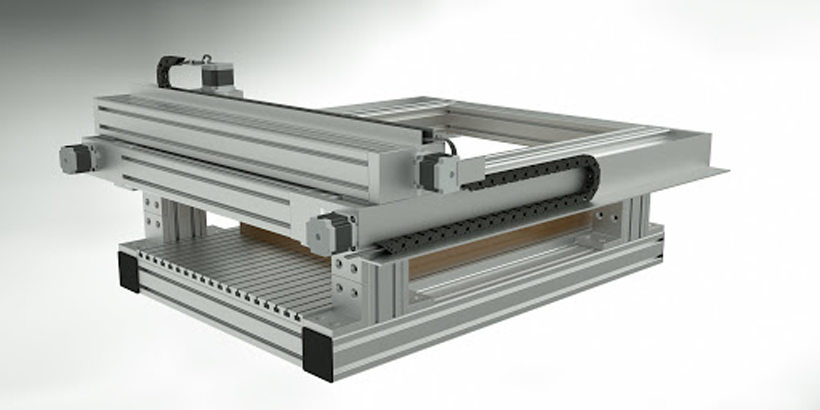
Despite the fact that there is no typical standard for the functions and specifications of the CNC component, taking into consideration the processing accessibility as well as trouble, some policies, as well as referrals, are typically used in actual scenarios.
Tolerance
Tolerance restricts the permitted dimensional error or border, it belongs to the materials as well as the geometry of the component, the conventional resistances are ± 0.125 mm (0.005″), however, some limited tolerance can attain ± 0.0125 mm (0.0005″) as well as also 0.0001″.
Hole size
The standard size (larger than 1mm) is recommended, look into the drill bit sizes as well as use a drill little bit to process a hole first and after that make use of a reaming or dull tool to complete the hole. Optimum depth (4 x nominal diameter) need to be used if you utilized the end mill to pierce non-standard size.
Thread size
The advised thread dimension is M6 or larger, which is cut with CNC threading devices, and also the string length is better in between 1.5 x small size as well as 3 x small diameter.
Thin wall components
It is suggested that minimal wall density for steel slim wall surface parts is 0.8 mm and also 1.5 mm for plastic parts, to make certain the product stiffness and reduce vibrations during machining, along with enhancing accuracy.
CNC Machining Design Restrictions & Tips
Before designing a part for CNC, there are some suggestions you can understand to speed up the process and avoid great deals of troubles.
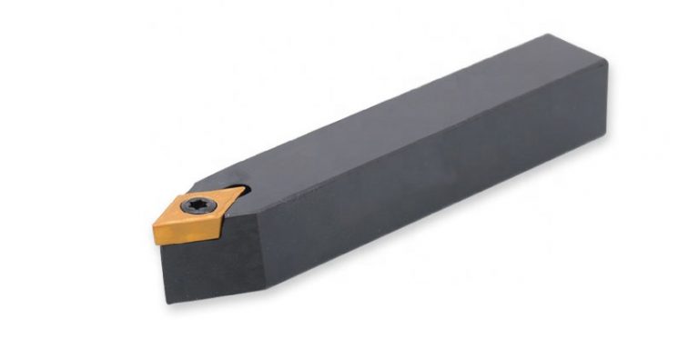
- Consider the geometry of the cutting tool utilized to remove material in the machining and also features you designed need to fit the handling method of the CNC machine.
- When designing a part with Scan2CAD, bear in mind to define the range of your vector photo, the system units can be set as millimetres. Minimize the vector lines to the most affordable number of nodes and also just export attracting components right into the final DXF data.
- Tooth cavity deepness ought to be under 4 times the tool size in order to minimize the machining troubles and also the possibility of tool damages.
- Since it minimizes the waste of material and also small attributes should be stayed clear of, Engraved message is better than embossed text.
- Attempt not to use certain resistances, since when calling for higher precision, even more time and also labour will be needed and also triggers raised expense.
- In CNC programs, all the dimensions and positions of surface areas, lines and factors are based on the programs beginning. It is much better to note the coordinate dimension directly on the part illustration or make use of the same information to introduce measurement as a lot as possible.
- The problems of geometric elements need to be full and accurate in programs.
- In CNC machining, the functioning procedure is typically concentrated, so it is extremely crucial to find the very same datum. It is usually necessary to set some auxiliary benchmarks.
